Another Step Toward CNC Programming Automation
Part designers and part programmers have to think differently. Esprit FX is a development from DP Technology (Camarillo, California) that helps overcome the "disconnect" that occurs when designers pass geometry to CNC programmers. FX stands for "feature exchange." It allows programmers using Esprit CAM software to receive information about the designer's original intent automatically so that part programs can be created more quickly and more accurately.
Share


Part designers and part programmers have to think differently. Esprit FX is a development from DP Technology (Camarillo, California) that helps overcome the ŌĆ£disconnectŌĆØ that occurs when designers pass geometry to CNC programmers. FX stands for ŌĆ£feature exchange.ŌĆØ It allows programmers using Esprit CAM software to receive information about the designerŌĆÖs original intent automatically so that part programs can be created more quickly and more accurately.
Part designers think in terms of geometry, whereas programmers think in terms of machinable features. Problem is, the programmer usually has to interpret geometry to define the feature to be machined. For example, the designer creating a pocket with islands sees each island as a geometric entity, because separate steps are required to define it. The programmer, however, sees the routines to mill around those islands as part of single pocketing operation on the CNC machine tool.
Likewise, the designer locates the center of a hole at a certain point in the solid model that represents the part. Then, the designer adds the diameter and the depth of the hole. For a stepped hole, two diameters and depths must be entered. If the hole is tapped, details about the pitch of the threads, the tolerances and so on must be noted elsewhere, because these details are not strictly part of the model. In most CAD systems, each step taken to create geometry is recorded in some sort of ŌĆ£feature treeŌĆØ in which subordinate details and related notes are arranged in a descending, branch-like fashion.
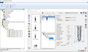
Typically, the programmer importing a design file into a CAM system sees only the solid model that represents the final part geometry. Although it may be obvious that a cylindrical void in the model represents a hole, the programmer needs additional information to determine the best way to machine it. The FX technology makes this information available by incorporating portions of the original CAD feature tree into the Esprit user interface. In the screen on page 56, the window in the upper left shows a list of part features corresponding to the part geometry at the right. Clicking on a feature in the model or highlighting a feature in the list calls up related information from the feature tree and presents it in the window to lower left. This information includes tolerances, material properties, surface finishes, administrative data and so on.
With access to this information, the programmer can begin selecting appropriate machining routines and parameters in Esprit. Because many of these routines and parameters are likely to be stored in a library or database (in this case, the Esprit KnowledgeBase), the programmer can ŌĆ£click throughŌĆØ this process very rapidly. According to Chuck Mathews, technology vice president at DP Technology, beta users have experienced a 10-to-1 increase in productivity for programming hole making operations.
Portions of the FX technology will be available to Esprit users in the latest version of the software. This includes initial capability in milling and wire EDM (electrical discharge machining) for solid models created in Solid Edge and Solidworks. Support for other major solids-based CAD systems is planned, as is feature exchange functionality in turning.
Related Content
Advanced Tool Paths, Simple Implementation
Programming advanced tool paths used to be a complex, time-consuming task. Canned cycles in CAM software have now made them more accessible than ever.
Read MoreBuilding A Powerful Bridge from the CAM Programmer to the Shop Floor Operator
SolidCAM for Operators provides a powerful bridge from CAM programming to the shop floor to best streamline the machine shop process with its CAM part simulation. It provides a clear picture to the operator for setup and prove-out, enables minor G-Code changes and avoids crashes, broken tools and scrapped parts.
Read MoreOrthopedic Event Discusses Manufacturing Strategies
At the seminar, representatives from multiple companies discussed strategies for making orthopedic devices accurately and efficiently.
Read MoreThe Power of Practical Demonstrations and Projects
Practical work has served Bridgerland Technical College both in preparing its current students for manufacturing jobs and in appealing to new generations of potential machinists.
Read MoreRead Next
AMRs Are Moving Into Manufacturing: Considerations for Implementation
AMRs can provide a flexible, easy-to-use automation platform so long as manufacturers choose a suitable task and prepare their facilities.
Read MoreMachine Shop MBA
Making Chips and 91╩ėŲĄ═°šŠ╬█ are teaming up for a new podcast series called Machine Shop MBA—designed to help manufacturers measure their success against the industry’s best. Through the lens of the Top Shops benchmarking program, the series explores the KPIs that set high-performing shops apart, from machine utilization and first-pass yield to employee engagement and revenue per employee.
Read MoreLast Chance! 2025 Top Shops Benchmarking Survey Still Open Through April 30
Don’t miss out! 91╩ėŲĄ═°šŠ╬█'s Top Shops Benchmarking Survey is still open — but not for long. This is your last chance to a receive free, customized benchmarking report that includes actionable feedback across several shopfloor and business metrics.
Read More


